by bassybeats | Jan 17, 2023 | Others
The pickup
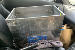
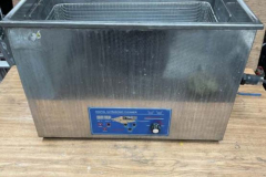
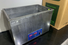
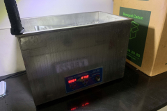
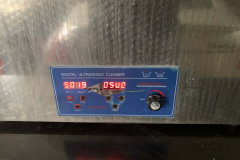
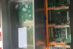
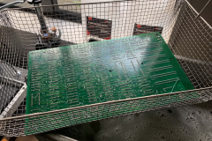
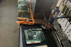
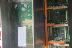
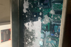
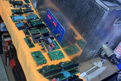
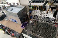
I was accumulating a very large amount old motherboards and computers with really bad corrosion that a toothbrush and iso wouldn’t remove. Keeping an eye out I saw a 30L ultrasonic cleaner online for a silly cheap price and I just couldn’t resist the challenge to get it going.
What the heck is wrong with this thing?
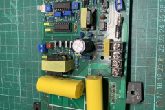
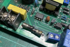
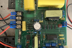
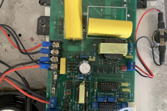
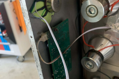
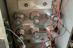
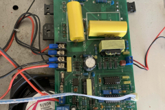
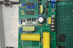
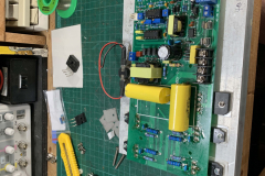
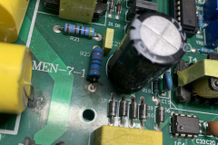
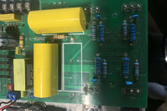
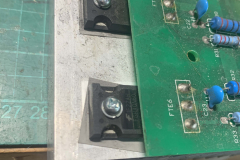
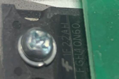
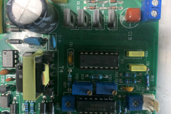
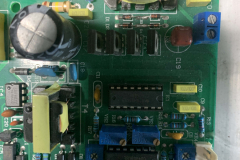
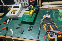
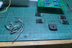
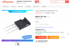
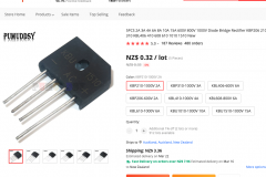
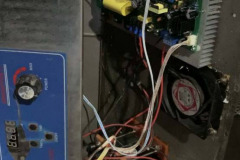
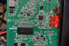
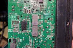
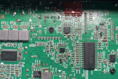
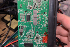
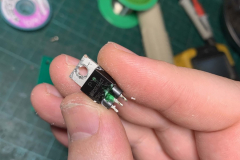
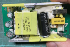
Turning it on, there was no life at all. Starting to pull it apart showed that all the fuses were destroyed and blown and there was a dead short on the driver PCB. Desoldering the power transitors and recifier and testing them showed that half of them were blown out, assuming from overheating over time. A quick order from AliExpress of the out of production parts later and the shorts were all cleared and it was time to try turn it on.
Its alive!
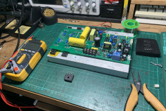
Fuses replaced, transistors replaced and all the wiring tidied up, it was time to try turn it on. It actually works! First time it fired up it actually stayed on and heated up water to 60C no worries and the transducers also worked for 10-15mins straight.
Putting it through its paces and finding problems
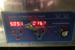
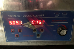
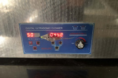
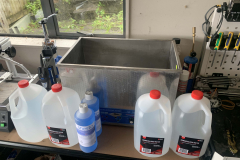
Finally ordered some proper cleaning fluid and purified water for it and loaded up the cleaner to 20L. It took like 40mins to heat up to 60C and then the transducers didn’t work! Turns out I never tested both functions at the same time. I let it cool down to 45C and everything started working so I think there is still a power draw fault or temperature fault somewhere which will need to be addressed when I next drain it. But for now, I just keep the temp a little lower and it functions perfectly fine.
by bassybeats | Jan 16, 2023 | Retro Gaming
The Project
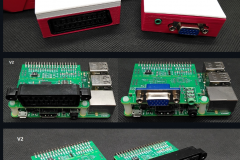
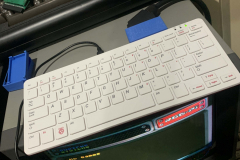
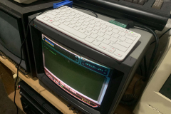
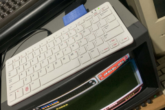
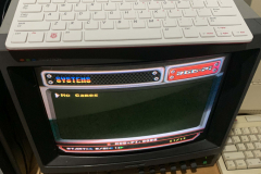
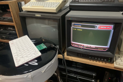
The Raspberry Pi has no ‘out of the box’ way to display a 240p RGB signal, which is a pain if you want to have RetroPie running on your 90’s Sony PVM. Enter, the Pi400RGB. Created by Llegoff on Github it offers either RGB Scart or VGA out from the Pi 400 or Pi 4’s GPIO pins. Only the first revision is available on the github which can make sourcing some of the parts a bit difficult.
Why are components so hard to find?
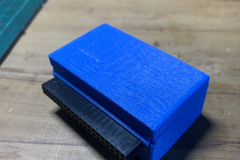
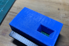
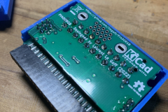
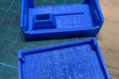
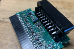
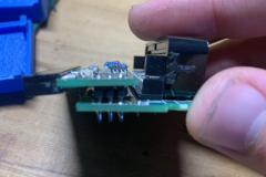
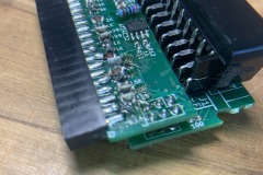
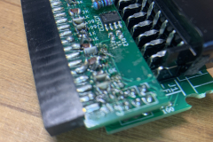
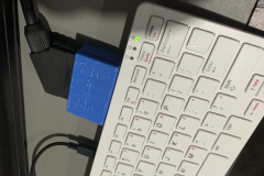
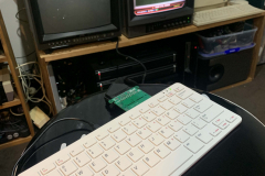
As per usual in 2022, parts were near impossible to track down. specifically the LTC1262 and the AT24C32’s in a SMD package. I think I had 3 attempted orders from AliExpress before I finally got some and I think I even ordered DIP versions by mistake as well. Coupled with the very annoying resistor values which I ended up joining some more common values together to get to the correct values as per the BOM. Without splitting the board and stacking it like in the photos it was a pain to get an output from it. I did try create a case for it that didnt involve cutting it in half but it didnt work out.
Deciding on an Operating System
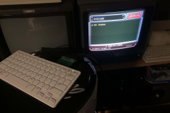
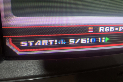
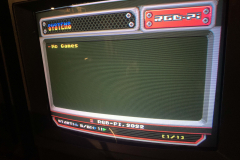
Once I knew it was working, I had to decide what OS to use. I tried Recalbox as it has built in support for the cable version of this but in the end I opted for the RGB-Pi OS from RGB-Pi.com. Much simpler and all the themes and visual assets were specifically designed for a 240p output.
by bassybeats | Jan 16, 2023 | Computing
The pickup
Trolling Trademe one night I did my usual filter of ‘faulty’ and this came up in the search results. It was a Sound Blaster X 2.1 Sound System at $1 reserve, I placed a $1 bid on it and woke up in the morning to find that I won it for a whole $1. A bit of postage and it was at my door and as expected, it did not work. Well it did, but it made a horrific popping noise and output no audio at all.
The Repair
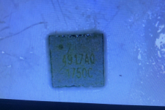
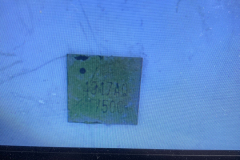
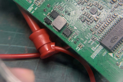
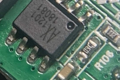
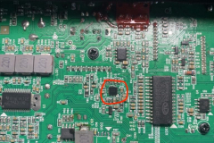
Digging into the repair I started with the power supply, making sure that all the voltages were present which they were. Next was the usual checking for shorts on the mainboard, all the caps checked out fine everything had the right voltages. Last test was the temperature test, does anything get unusually hot when powered on. And sure enough I found the issue the SGM4917 Headphone Amplifier Chip was totally shorted. After desoldering it with the hot air station the shorts on the pads all disappeared so it was a fairly good bet the chip was just fried. I ordered some new ones from AliExpress, dumped a huge amount of flux on the board and put the new chip on. And low and behold it works totally fine!
The Result
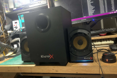
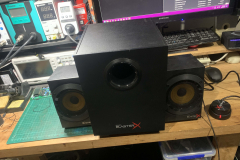
After buttoning everything back up again I cranked through some HipHop to check everything was working correctly before installing upstairs into the Projector room.
by bassybeats | Jan 16, 2023 | Retro Gaming
Finding out this thing even existed
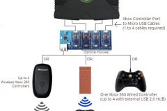
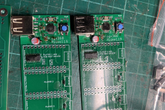
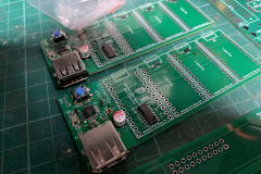
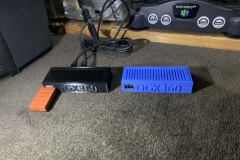
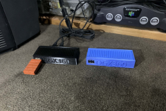
I think it was a post of a Facebook group of someone building one of these that led me to finding out about them and then the project sat on my to-do list for months before I ordered the parts for it. Its called the OGX360 by Ryzee119 on Github. Only to discover that the parts are all out of stock everywhere or obsolete. Took months of scouring AliExpress and Mouser to get everything together to start.
Sourcing the parts and painfully putting it together
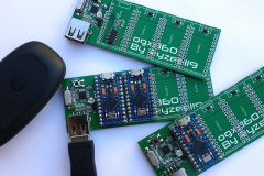
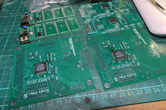
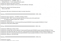
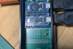
Finding the USB Controller chips and the fuses were the worst part. Once I had them in hand it was fairly straight forward to solder altogether, albeit a bit fiddly working with the small parts. Once soldered, I ended up digging through the GitHub and found this beta version of a GUI flasher software that basically lets you plug it in via USB, hold the reset button and click program assuming you have the GUI setup with the correct files etc. I managed to flash 3/4 of the modules with one of the ATmega modules being DOA and I had to order a new one.
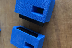
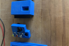
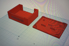
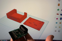
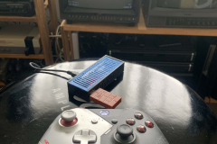
Printing some cases and testing them out
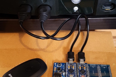
I did the initial testing with a wired Xbox One Controller and it worked perfectly. I then ordered the 8bitdo USB receiver to be able to use the Xbox One Controllers.
The STL I used for the case is this one
by bassybeats | Jan 16, 2023 | Others, Retro Gaming
Finding the Project
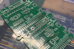
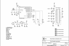
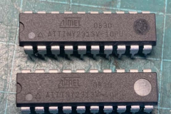
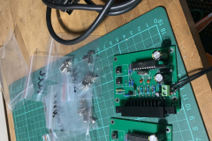
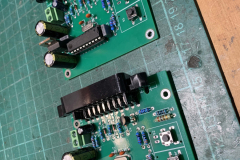
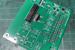
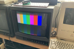
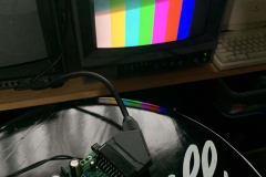
After seeing the 240p test suite everywhere I wondered if a standalone RGB test pattern generator existed, and sure enough as usual someone has already figured it out. I found this project on ‘AVR Projects by Dim’ that uses an ATTiny 2313 chip to generate 13 image patterns and a 1khz sound tone. So as usual I ordered some boards.
Figuring out what I did wrong
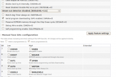
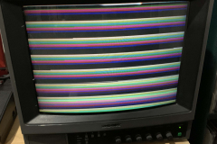
Other than finding the 2313 chips, everything else was pretty easy to put together. Programming it was easily done with the TL866 II programmer and using the included fuse settings. And then I found a problem, there was no sync on any of my PVM’s. Trolling through the comments, it became apparent I was not the first one to have this issue. I found the below comment buried in the comments.
“Try to change speed of clock with Quartz as close as possible to 21 Mhz. I’d had the same problem and I change a quartz with 20.8333 Mhz and now the generator works OK !
With 14,880 Hz is the Sync too slow for cca 5% ! Now with faster quartz I get 15,500 Hz Sync wich is within 1% of tolerance to needed 15,625 Hz.”
So I needed a 21mhz crystal, easier said than found. But as usual it was AliExpress to the rescue again. Ordered a bunch of crystals either side of 21mhz just to be sure, but I put it in and it ‘just worked’.
Getting it working and boxing it up
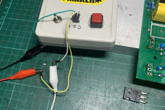
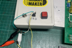
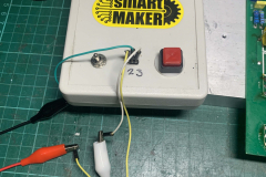
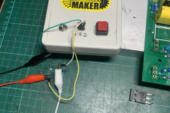
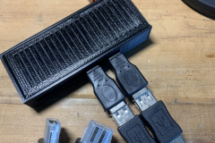
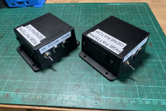
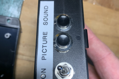
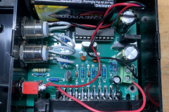
Once it was working I just had to find a box, some from Jaycar suited well and it was just a matter of cuttings some holes. I opted to externally mount the buttons and run it all off a 9V battery ( even though it wanted 12V, its regulated to 5V anyway ).











Recent Comments