by bassybeats | Aug 22, 2021 | Computing
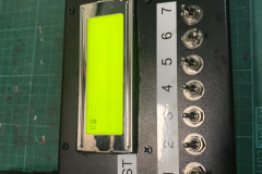
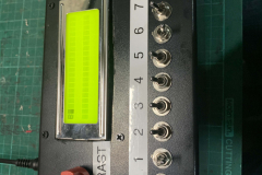
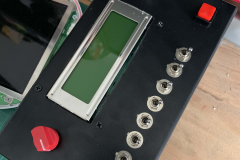
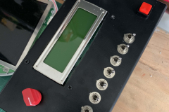
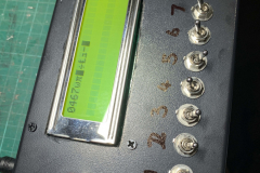
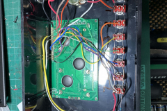
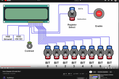
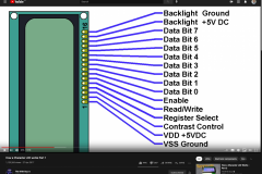
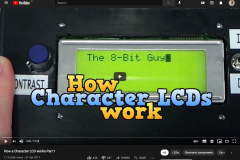
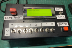
After seeing a video by the 8BitGuy on how an LCD Display works I remembered I had a bunch of 20×4 LCD screens sitting in a box and most of the parts and figured I could use some of these old parts up and make on one these boxes. I basically followed the tutorial in the video and wiring it up directly how he did.
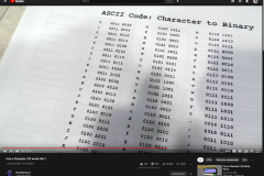
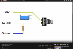
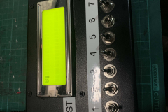
Wiring it up was pretty straight forward although I did run into a few issues that were explained in the video. I did not realise that binary numbers read LEFT to RIGHT, 7 to 0, not the other way around so Although I could get the capital letter B to work no other characters worked ( Capital B is the same backwards and forwards incidentally ). This is when I realised I wired it up backwards and had to reverse the switches left to right and make a new label. Another thing that was discussed in the video was the value of the resistor that pulls the enter switch to ground, I used a 100k resistor at first and realised it was too high, I then dropped it to 10k or 1k ( cant remember ) and tested the button and when you press the button it would over come the ground and give the switch 5V as expected.
So all in all a pretty cool little build and a cool little learning tool for understanding how binary works and how LCD displays work. Now I just have to remember all the 1’s and 0’s to make it work!
by bassybeats | Aug 22, 2021 | Computing
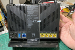
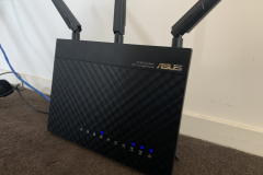
After getting stuck with a new internet provider and no router for weeks I decided to get an Asus RT-AC68U off trademe to both have a router and to get better performance and more control. The router was performing great for months until it started having random power offs and not coming back up with the correct IP address. I would have to power cycle it numerous times to get it to come back up and then it may only last for a few days before it did it again. I looked in the logs and there wasn’t anything specific but everything pointed to either faulty hardware or corrupt firmware. I swapped over the the ISP provided router that eventually turned up and attempted to update the firmware, then the issues began.\
Updating the firmware
Well updating through the UI just was not working, every time I tried to upload the official Asus firmware it would just error out and say the file was not compatible, even trying 3rd party firmware gave the same results. There were 3 options for me to try:
With no positive results I decided to strip down the device and see if there was anything obvious wrong with it ( overheating etc ). Nothing came of that but at least I could see the Serial port to program it if I needed it.
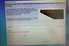
I did some more digging and found that there was an Asus Firmware Restoration tool for Windows, this was promising. To use the tool, you had to put the router into recovery mode but holding the reset button then pressing the power button and keep holding the reset button until the power LED starts flashing slowly, then you open the software, plug in an ethernet cable directly to the router and upload the firmware.
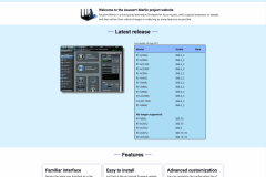
I tried multiple versions of the firmware with little success, all of them failed to upload. I eventually got one to upload and the router kicked back into life. One last issue I was facing is that the settings were all messed up and still giving errors. Turns out even after a firmware update the flash BIOS still holds the settings! You need to hold WPS button while powering it on until the power LED flashes fast, then you let it go and leave it until the unit comes back up. This is how I ultimately fixed it and got it to run the aftermarket Merlin Firmware as after the flash BIOS was reset I could successfully upload the Merlin Firmware using Asus’ tool and it has been stable ever since.
The working unit after months of being powered on with no issues.
Here are all the files I used to do this if anyone needs them.
by bassybeats | Aug 22, 2021 | Retro Gaming
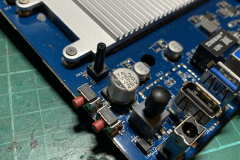
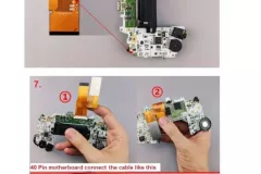
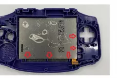
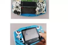
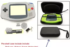
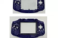
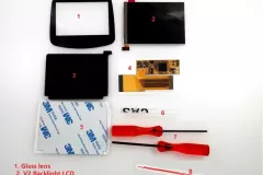
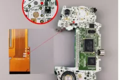
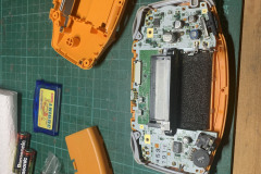
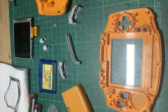
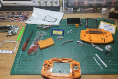
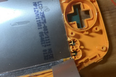
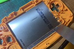
Just a short one this time. I picked up a cheap Gameboy Advance but instantly realised how awful the screens were, something that I wasn’t aware of as I had always had PSP’s. But a quick search on AliExpress surfaced this upgrade kit which was exactly what I was after. This instructions were non-existent, even though the seller said they would send them afterwards I never got anything.
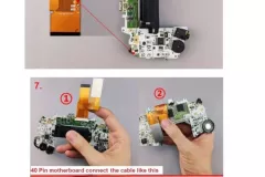
Luckily the kit was good and I could just reference the photos on the listing to figure out what parts of the plastic to cut out. I opted to leave out the brightness mod and have it full brightness all the time.
by bassybeats | Aug 21, 2021 | Computing
As part of my want to recreate some of my earliest machines growing up I thought I would go back to the very first one, a 486. It was a hand me down desktop style with Windows 95 on it. I don’t think I had it long before I upgraded to a Pentium 100/120.
Retro collection day pickup
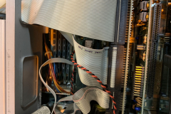
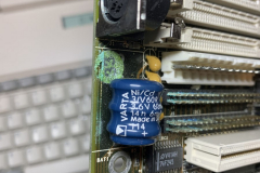
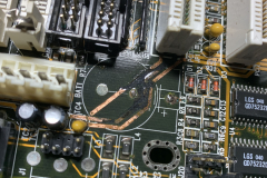
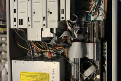
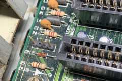
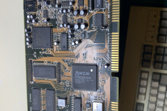
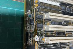
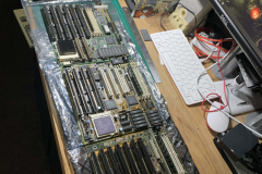
It wasn’t really going to be a reality until I saw a pair of machines at the retro tech sale in Onehunga just before the very first covid lockdown. Sadly I couldn’t open them up properly to look inside other than seeing they had 486 chips inside. Once I got them home as well as some ram I could open them up and see the horror that awaited me. Both boards had bad battery damage and were completely non functional, at least the cases, power supplies, floppy drives and expansion cards were all in working order. Lucky for me, one of my fellow retro gamers had found some 486 boards at the same sale that he gifted me to get me up and running with a 486, as well as a VLB video card.
Bulk chip pickup
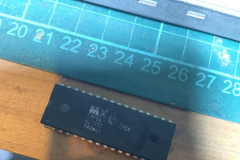
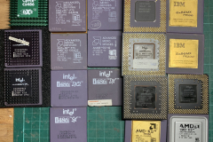
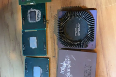
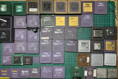
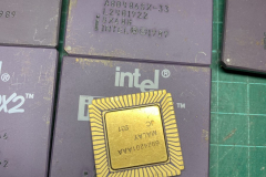
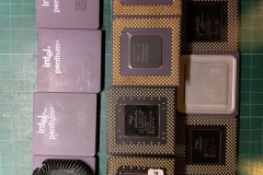
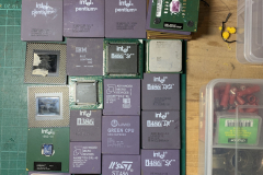
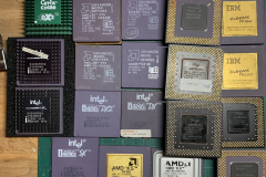
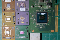
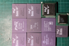
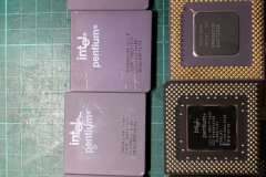
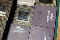
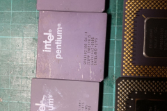
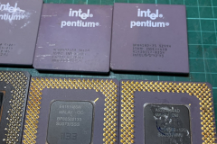
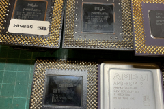
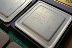
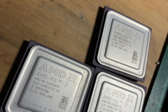
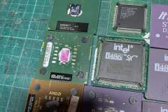
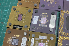
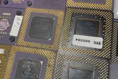
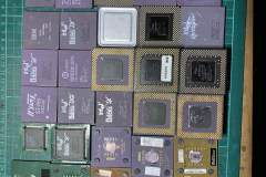
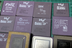
As a bit of a fluke purchase I spotted a listing for 3kg’s of CPU’s. Everything from Pentiums, 486’s, Pentium Overdrives and more. A lot of the chips had bent pins as they had clearly been sitting in a box/bin for years. It wasn’t overly cheap but I managed to remove some of the double ups and get all my money back, essentially making my ones free. These chips will give me a good base to test from.
Round 1 of repairs
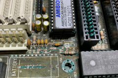
The first round of testing went so so. A lot of the boards that I had were battery damaged. One of the the hardest parts of diagnosing these boards was actually finding the manuals to get the jumper settings for each board. Some of them I just couldn’t find anything on them so I had to resort to putting a less ideal chip in them to see if I got any post codes come up, if only to get a model number or something to be able to look up. I did managed to get 4 boards going on this round.
Chip damaged
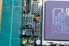
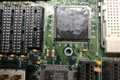
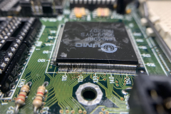
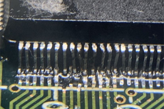
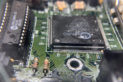
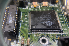
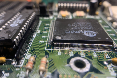
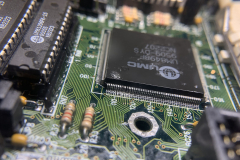
I did manage to track down a fairly unusual issue. Upon closer inspection of one of the boards I was given from my mate, the main chip was actually not connected to the board at all, and on even closer inspection, it looked like it had been hit but something and bent a few pins/ripped some traces. I did attempt to reconnect these pins but had no success getting the board to work.
DOS Setup
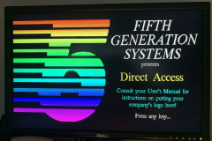
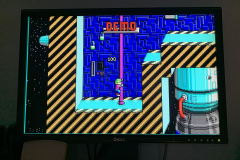
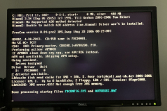
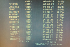
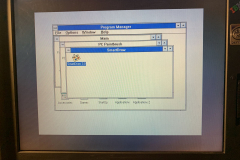
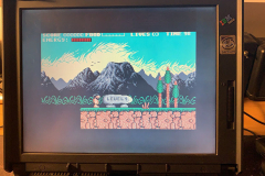
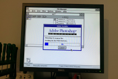
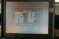
Once I had two boards working for the two cases I picked up I loaded up my DOS image and got everything working.
Repairs Round 2
About 8 months after a few other projects I decided to revisit the boards and see if I had learnt anything and if I could get any more going, or at a minimum get rid of the ones that I couldn’t get working. Turns out I did learn something. Out of this batch I managed to get 5 boards going. Some of the issues I had were:
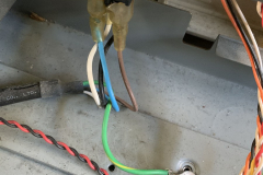
- no power on some of the rails ( bad solder joints )
- wrong ram used ( more on that below )
- Finding a CPU that worked with the board. I found that the IBM DX2 ( Cyrix chip ) seemed to be the most compatible for some reason. Once I got it booted I could then take note of the board/bios to do more googling
- bad keyboard chip
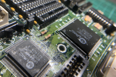
- Missing traces that I missed the first time around. This time I had a digital microscope to be able to get a much better look at the damaged traces.
- corroded pins on bios and other chips which I fixed by tinning them with solder.
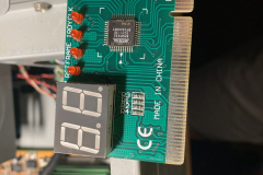
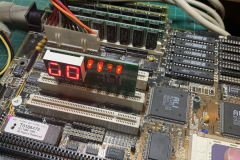
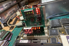
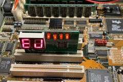
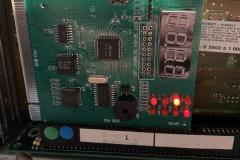
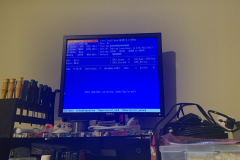
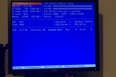
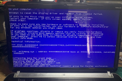
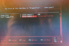
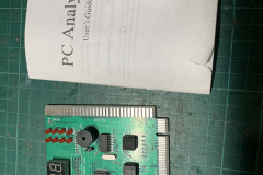
So it was a good second round of repairs. Sadly I still had 3 boards that showed no signs of life. They all showed power, and the bios read good but the reset line just stayed high and the post code reader showed 00. Something that I found out this time around was that the 4 digit post code readers actually are just two 2 digit readers, with the ones on the left being the current code and the ones on the right being the previous code. This made diagnosing it much easier as I could actually look up the code and know what the issue was ( like things in the 80’s being keyboard related and low error code being ram issues ).
Ram Discovery
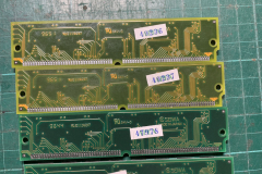
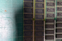
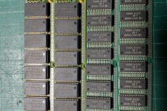
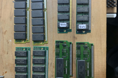
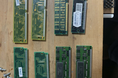
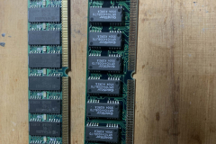
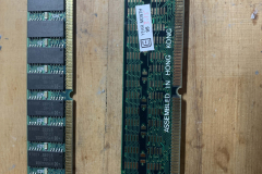
One likely obvious thing I discovered this time around which was likely a big part of the success was that there is actually two types of 72pin SIMMS. EDO and FPM and that ‘most’ 486 boards only support FPM modules. Even externally they are not easy to tell apart but I saw something on a forum that if the part number of the chips ends a 0 (zero) it will likely be FPM and if it ends in a letter it will likely be EDO, something that checked out for all the modules that I had. I had no luck with the 30pin modules, which was likely a jumper issue and a lack of manuals available.
Final working boards and machines
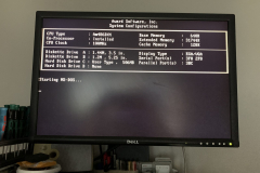
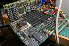
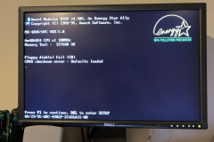
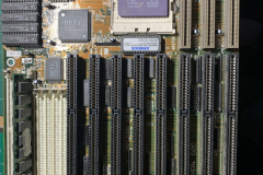
So out of the full set of 10 boards I ended up with 7 that work in some way or another, my base level is, if it posts to a bios screen I consider it a success for now. The 7 boards are:
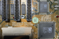
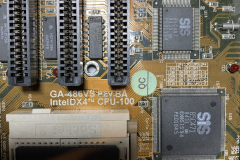
- A Gigabyte GA-486VS with an Intel DX2-50, 16MB of ram and 256k of cache
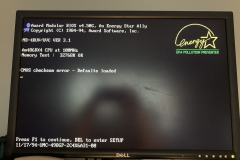
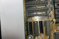
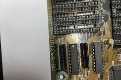
- An MB-8433UTC PCI board with an AMD DX4-100, 32MB ram and 256k of cache
- An unknown OPTI chip board with a DX4-100, 16mb of ram and 256k of cache
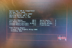
- An HD4077D board with an Intel 486 DX2-66, 8mb of ram and 256k of cache
- An AL 486 board with a DX4-100, 64mb of ram and 256k of cache
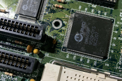
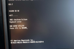
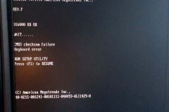
- An unknown ALI M428/M431 based board with an IBM Lightning DX2-50, 16MB ram, no cache and still has a keyboard detection error
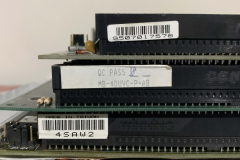
- An MB-4DUVC-P-AB board with a DX4-100, 64mb of ram, 256k of cache
The two full machines are both loaded with my DOS Image:
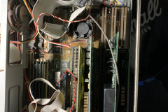
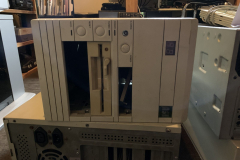
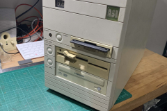
- The small tower with the MB-4DUVC-P-AB board, DX4-100, 64mb of ram, 256k of cache, Creative Vibra 16 ( with CD Drive on the IDE header ), Dual Compact Flash to IDE adapters, I/O card,1.44mb 3.5″ floppy, 1.2mb 5.25″ floppy, and a Western Digital WDC WD90C33-22 VLB video card
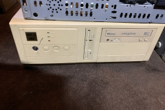
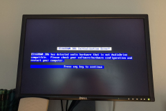
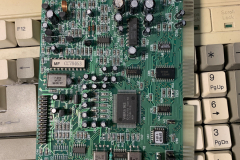
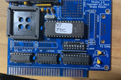
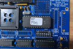
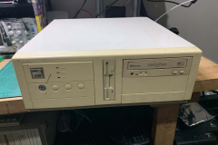
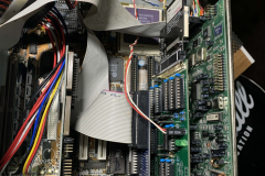
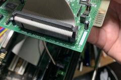
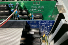
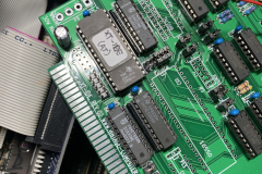
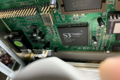
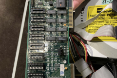
- The desktop with the MB-8433UTC PCI board, AMD DX4-100, 32MB ram, 256k of cache Soundforge Vibra 16S, ISA Floppy Disk Controller by Sergey Kiselev, 1.44mb 3.5″ floppy, XT-IDE Rev 2 board and a S3 Virge Trio64+ PCI video card.
Final non-working machines
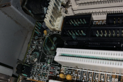
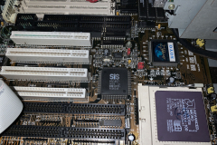
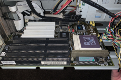
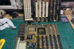
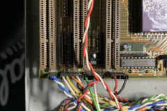
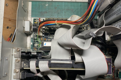
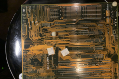
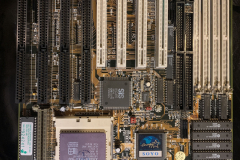
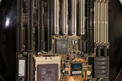
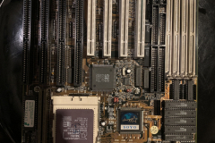
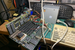
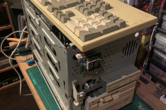
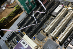
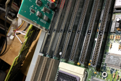
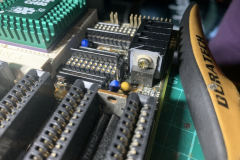
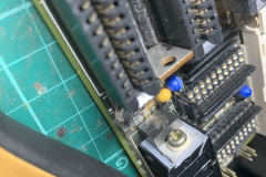
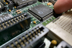
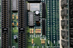
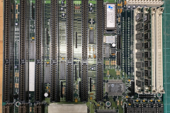
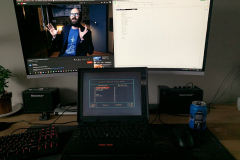
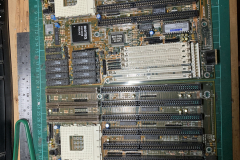
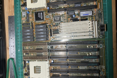
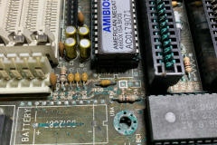
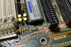
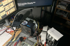
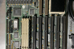
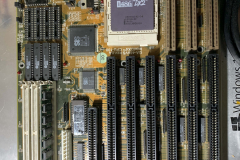
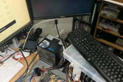
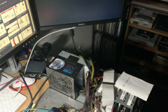
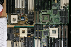
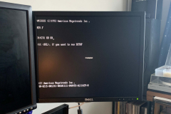
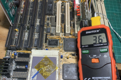
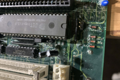
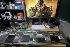
As for the non working boards, I actually got one of them working in the photo, so I am left with two PCI boards and another MB-4DUVC-P-AB with the bent pins/traces. These showed no signs of life and with 7 others I figured i’d move past them and onto other projects.














Recent Comments