by bassybeats | Oct 30, 2025 | Computing
With the annoyance that is Windows 11 I have finally started to migrate my PC to Linux, I decided on base Debian dual booted with Windows 11.
The dual boot
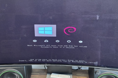
I really wanted to get the theme of dual boot splash screen the correct resolution with rEFInd but my Samsung monitor or the bios doesn’t like it and you get a black screen so i opted for a basic them and simple 1024×768 for reliable booting.
Corsair iCue headaches
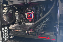
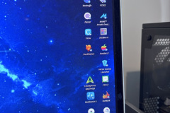
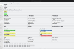
Last time I tried to do this booting off a different drive the biggest issue I had was I could not get any software working that could control my Corsair iCue devices. Both my Corsair commander fan controller and the H100i AIO cooler weren’t working. This time I stumbled across OpenLinkHub. This software just worked. It controls all my fans and AIO rgb just fine. I did have to change my rear fan to a PWM fan to get it quiet.
Other software fixes
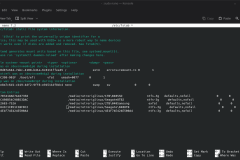
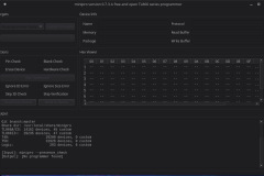
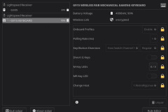
Some of the other annoying issues i had to fix included adding the NTFS and exFAT drives to the fstab file so they are mounted on boot, I have no idea why you can’t do this in the GUI of debian. I also had to install Solaar to control my Logitech G915 keyboard and G305 mouse, you have to change the G915 to on device settings for the RGB settings to stick between dual boots on Windows and Debian. And I had to get Open Super Clone and MiniPro GUI for my programmers and HDD imaging.
Software choices
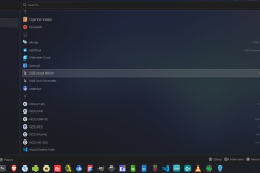
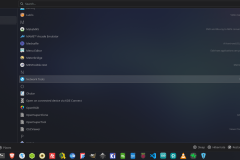
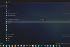
Some of the notable Windows –> Linux change overs are:
- Rufus – WoeUSB-ng
- Putty – Zutty
- CPU-Z – CPU-X
- TreeSize – Disk Usage Analyzer
- Guitar Pro – Guitarix
- GPUZ – GPU Viewer
- Notepad++ – Kate
- Crystal Disk Mark – KDiskMark
- MSI Aferburner – LACT
- Logtech GHub – Solaar
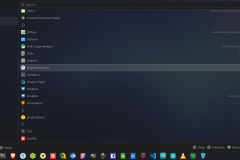
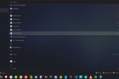
- iCue – Open Link Hub
The only daily thing I have not found a solution to is Google Drive, inSync looks the best but I don’t feel like paying for it.
by bassybeats | Oct 30, 2025 | Computing
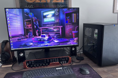
Time for a new variation of the dual XP and Windows 10 workshop PC.
Hardware
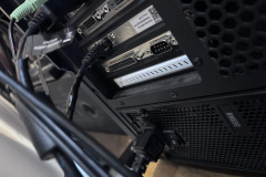
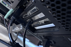
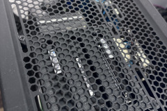
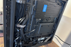
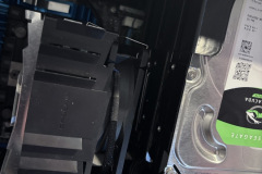
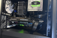
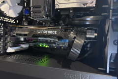
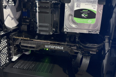
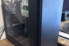
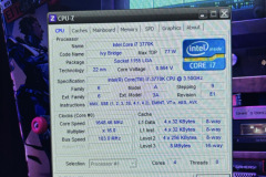
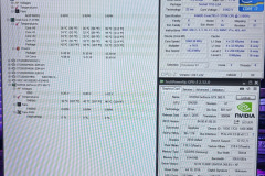
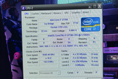
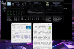
This time I have gone for mATX in a Fractal Design Mini C, a Asus Z77M-Pro, i7 3770k, 16GB DRR3 1600mhz, GTX 980ti. To move over all my harddrives I had to 3D print a top 120mm fan mounted 3×3.5″ sata drives. Inside I also have a 2.5Gbe network card and a PCIe parallel/serial card to allow all my programmers to still work. I chose the Z77 as it has built in USB3 and 3rd gen support and overclocking support. But finding a Z77 board in mATX was really hard and I had to get it expensive from AliExpress. This Asus board is still extremely fussy with ram too, none of the fancy corsair, gskill ram worked, it has the plain kingston ram in it and works fine.
XP install
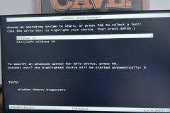
Nothing too special with the XP install, the SSD just moved across from my last install. I had to change the sata controller over to IDE mode and it booted fine. Reinstalled the GPU drivers and chipset drivers and it was good to go. The only thing that doesnt work is the 2.5Gbe card as there are no compatible drivers.
Windows 10
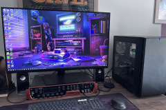
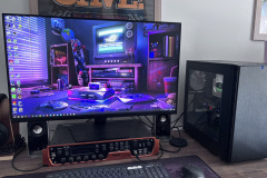
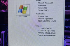
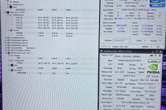
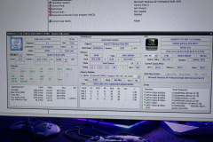
Nothing special here, all the regular stuff, just the specs in the photos.
by bassybeats | Oct 27, 2025 | Wood Working
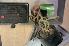
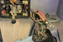
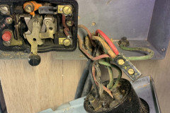
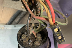
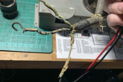
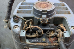
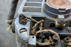
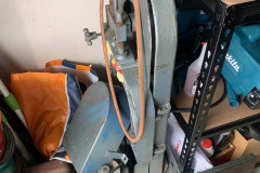
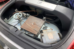
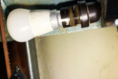
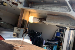
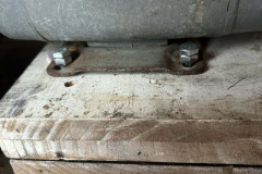
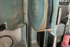
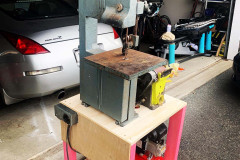
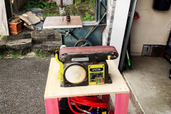
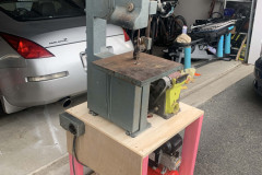
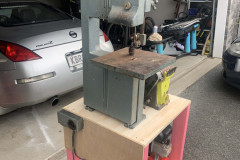
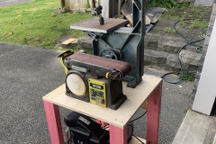
I inherited an old bandsaw from my grandfather which worked but needed serious TLC. The wooden stand was trashed and the belt mounting was non-existent. Time to make a new one. Didn’t help I had to fit it in the back of a 350z..
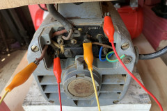
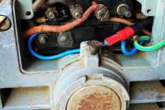
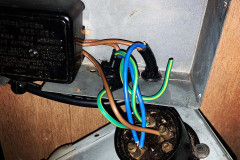
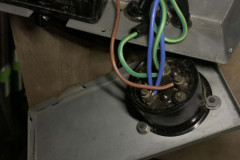
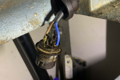
Fixing the wiring
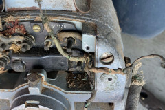
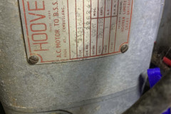
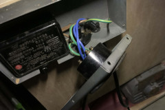
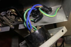
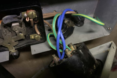
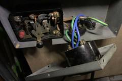
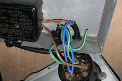
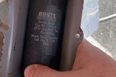
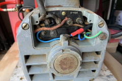
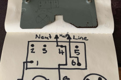
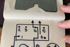
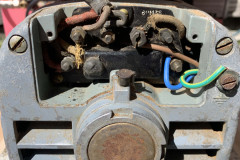
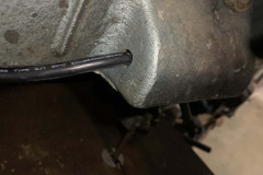
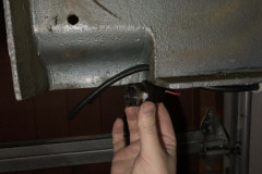
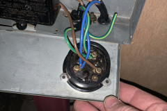
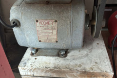
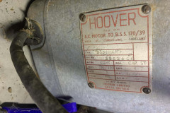
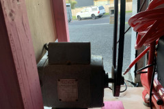
Before i start with a new stand, I had to address the awful wiring. I replaced basically all of it with modern wiring, luckily the motor cover had a wiring diagram on it to determine what direction the motor spins so I could reverse it to have a more compact stand.
New frame and adding a sander
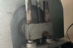
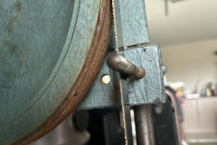
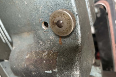
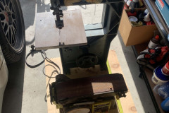
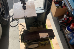
I opted to use 18mm plywood and 100x50mm timber with locking caster wheels to make it easier to move around. It is all mounted with T-nuts to make it easier to dismantle. I added a new blade at the same time, but I had to move the cover bolts to get the shorter, thicker blade installed.
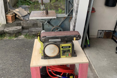
I also added a belt sander on the other side since I reverse mounted the motor under the machine. Having the lower space underneath also gave me space to put my air compressor as well making it an all in one portable setup. The only thing that is left is to remove some of the vibration which I think is belt or blade tension related.
by bassybeats | Oct 27, 2025 | Retro Gaming
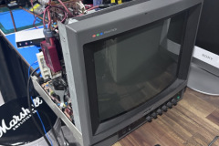
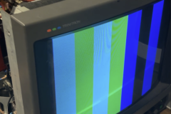
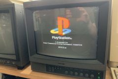
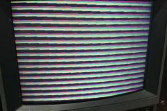
So after moving house, my PVM developed an issue where it would intermittently show the red in the picture. It took a while to figure it out as I thought it was just a loose connection but it seemed to be something internal.
The symptoms and fix
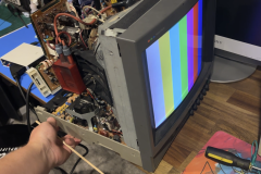
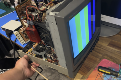
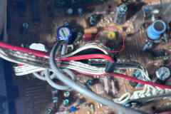
After I realised it was an internal issue, I finally could reproduce it by pushing up on the back of the casing and could introduce the issue consistently, this proved it was either a loose connection or a cracked solder joint and not a bad red beam in the CRT itself.
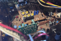
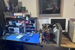
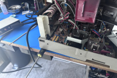
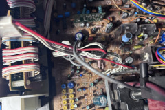
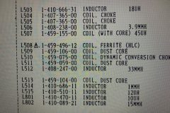
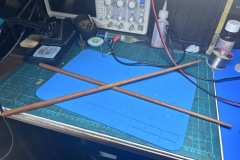
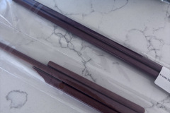
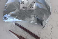
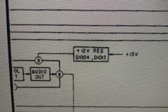
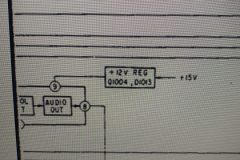
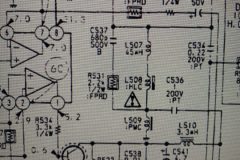
Once I figured that out.I had to find a way to isolate the issue, I ordered some cooking chopsticks on AliExpress so I could poke around the board while it was powered on without risking shocking myself. After reading the schematics and finding the likely area, I finally found that it was the daughter board carrying the signal that was socketed into the mainboard. I powered it off and removed it, put contact cleaner in there and put it all back together and the problem went away.
An Audio side quest
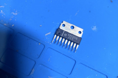
While I had it all part I figured I would address the missing audio. I did replace a few of the caps in the audio section with no success and determined it was the op-amp itself. I ordered a new one and the sound all came back in its mono glory.
by bassybeats | Oct 27, 2025 | Retro Gaming
Everyone knows how annoying it is to charge PS3 controllers, you have to have them plugged into a PC or the PS3 itself powered on, well I attempted to work around that.
The solution
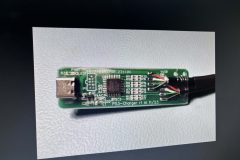
A while ago, I came across this Github project thats aimed to solve this issue by using an ATmega chip and USBC. The PS3 controllers use USB handshakes before they will start to charge, which is why only a PC or PS3 will charge them. This github project, uses the ATmega chip to initiate the USB handshake and the start charging up to 4 controllers via a USBC input.
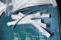
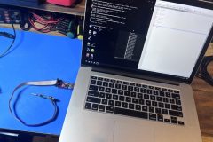
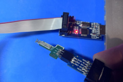
Safe to say, the project was more annoying that I expected it to be. It uses 0402 SMD parts and an annoying way to program the chip using pogo pins ( of which you needed to make a custom adapter for, AND the you still had to solder on wires anyway. I think in future the PCB should be redesigned to use normal pins for programming as there is actually enough space.
Programming
This was buy far the worst part of the project, the github had very little detail on how to actually program these chips and to get the 12mhz internal clock signal calibrated correctly. I did ask some questions on the github but ended up writing my own instructions.
STEP 1: Connect the Programmer
Make sure your programmer is wired to the ATmega328PB correctly:
MISO → MISO (pin 18)
MOSI → MOSI (pin 17)
SCK → SCK (pin 19)
RESET → RESET (pin 1)
VCC → VCC (pin 7 or 20)
GND → GND (pin 8 or 22)
STEP 2: Check Current Fuse Settings
Open your terminal and run:
avrdude.exe -C”avrdude.conf” -v -patmega328pb -cusbasp -U lfuse:r:-:i -U hfuse:r:-:i -U efuse:r:-:i:i
You’ll get something like:
lfuse: 0x62
hfuse: 0xD9
STEP 3: Calculate New LFUSE with CKOUT Enabled
https://eleccelerator.com/fusecalc/fusecalc.php?chip=atmega328p
That becomes: 0x22
STEP 4: Program the New LFUSE
Run:
avrdude.exe -C”avrdude.conf” -v -patmega328pb -cusbasp -U lfuse:w:0x22:m
Now CKOUT is enabled. The system clock will appear on PB0 (pin 14).
STEP 5: Measure the Clock Output
Connect a frequency counter or oscilloscope probe to PB0 and GND.
You should see a signal close to 12 MHz.
If not exactly 12 MHz, that’s expected — the internal oscillator needs calibration.
STEP 6: Calibrate the Internal Oscillator (OSCCAL)
In your firmware:
Use a loop that outputs a square wave (e.g., toggle a pin).
Adjust the OSCCAL register value (0x00 to 0xFF) until the frequency on PB0 is as close to 12 MHz as possible.
STEP 7: Compile with Atmel Studio 7
Import ps3-charger.c into Atmel Studio and compile to a hex file.
You should enter the clock signal into the source code from earlier
STEP 8: Flash to ATmega328PB
Connect programmer (e.g., USBasp), and flash the new file, for example:
avrdude.exe -C”avrdude.conf” -v -patmega328pb -cusbasp -U flash:w:ps3charger.hex
avrdude -c usbasp -p m328pb -U flash:w:PS3-Charger-C7-250.hex
STEP 9: (Optional) Restore LFUSE to Disable CKOUT
Once calibrated, you can turn off CKOUT to regain use of PB0.
If your original lfuse was 0x62, restore it:
avrdude -c usbasp -p m328pb -U lfuse:w:0x62:m
Files can be found here
Testing them out
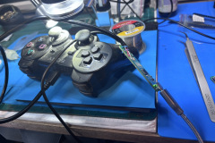
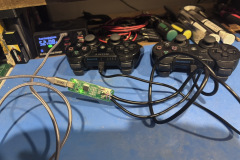
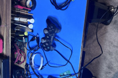
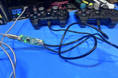
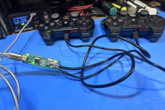
After programming them finally, I found that it didnt work very well with just 1 controller plugged in, the timing or capacitance on the USB lines must not be right, 2 controllers always started charging immediately. There is some notes in the schematic to fix that for a new revision they never got around to I guess.










Recent Comments