This article was suppose to be two different articles but I took so long to do them that I ended up making a new pedal board and thought I would just create one log entry for them both.
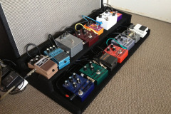
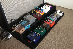
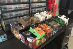
As usual I have made to many of something and I wanted to have a pedal board for home that would accommodate originally 14 pedals but now I have moved it down to 10 pedals.The main reason it needed to be so big was I had made so many pedals in the past and I wanted to be able to try different combo’s together without having to unplug stuff all the time. I know i’m lazy.
Pedal board version 1
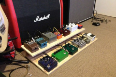
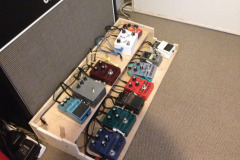
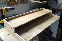
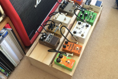
I had no idea how big it needed to be, luckily I had some scrap bits of plywood left over from another project so I just stacked a couple of bits of wood and laid the pedals and cables out for sizing. Seemed I guessed pretty well.
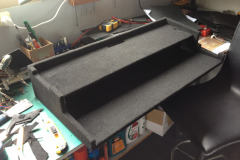
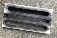
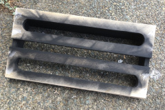
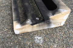
A bit of wood working and I had a rough working pedalboard. It looked rough but I was going to fix it. I ended up routing some holes to get the power and instrument leads through but it was more of less on point.
I did have some carpet left over from when I built the subwoofer box in my car years ago, so that worked perfectly. Although after having it on the floor a couple of years the carpet got really dirty, i’d probably use something else in future.
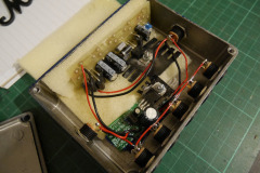
I went for the Tonepad power supply board with some changes. It seemed that all I need to be change to get higher current limits were the diodes and the voltage regulator to a LM350 adjustable. The input power was just a 24v laptop power supply with a 3.4A limit, plenty for all my pedal needs. I also added a Jaycar daughter board to get a single 12v tap for the odd pedal that needed it ( old boss stuff in my case ). Even though there is 5 9V outputs, I still made up a daisy chain cable and could have just used a single output.
Pedal board version 2
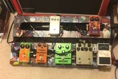
The last pedal board project ( above ) I made was not small or portable, I aim to fix that with this version as well as make it look way cooler and be much quieter using isolated power supplies
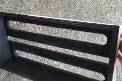
So far with the build I have made a few modifications since last time. The biggest one being having slots under and above the pedals the route all cables downwards and out of the way. I have also reduced the size to allow for 10 pedals, two rows of 5 is better than 14!
How to keep them fixed
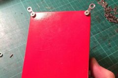
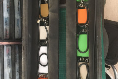
I got a great idea from dad, he hand made little alloy tabs to go between the pedal case and the bottom plate. A quick look around and some old bike chain works a treat!
{gallery}galleries/new-pedalboard/fitting{/gallery}
Power troubles
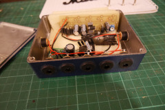
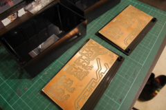
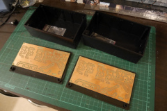
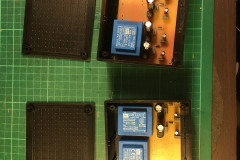
Another lesson learnt from the last project was to isolate the power supplies as the higher gain pedals tend to leak into the singal chain of others if they are sharing common power. This boards are now etched and I am just figuring out how to mount it all in. The plastic boxes seemed right but the boards are a few mm too big.
Comic book covering
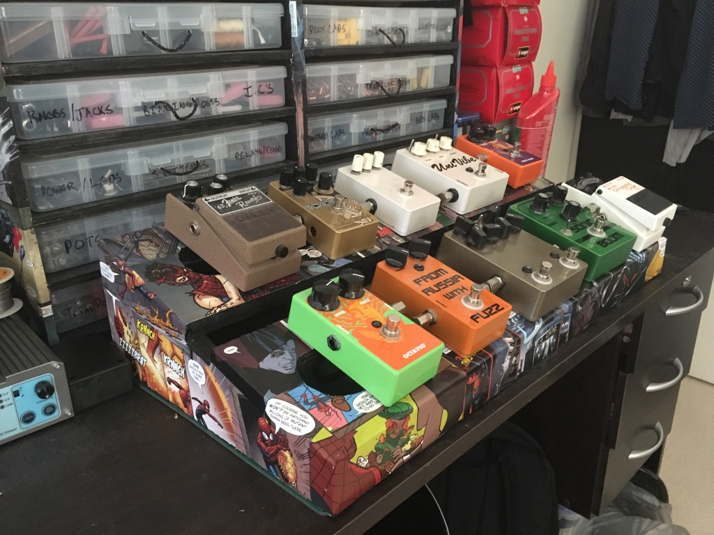
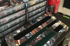
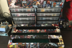
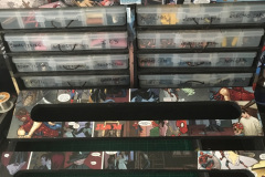
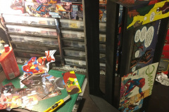
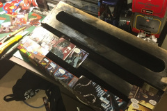
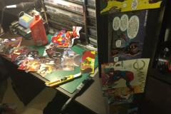
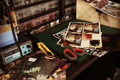
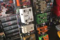
After the success of a couple of my last projects with the comic book page covering I decided to do something a bit different this time. I still had some left over and the carpet of the last one invited a lot of dust to accumulate on it. It was the same process to get the comics covered all over the unit.
Isolated power supplies
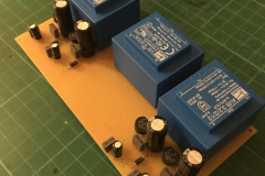
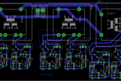
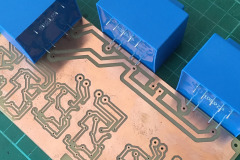
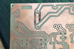
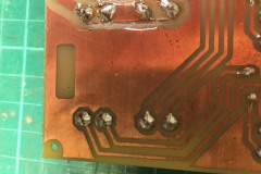
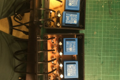
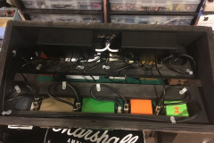
Again, after speaking to my dad on how we built his, we decided to make custom PCB’s for the power supplies for my rig as well. The hard part with this build was that a lot of the pedals had different voltages and different current limits. The Univibes wanted 15-18v DC, the other pedals wanted 9v and the tube over drive wanted 12v AC. We ended up designing them so that I could swap out a voltage regulator for different outputs and swap out different transformers for higher voltages. A couple of issues I ran into was that the TO-92 regulators couldn’t supply the current for some of the pedals so I had to rig in some larger regulators and the transformers I bought had an extra pin on them that I had to cut a trace on the PCB’s to make them work. The supplies also directly run off 240v AC wall power so you need to be careful and I ended up running a fuse for each box.
Final assembly
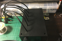
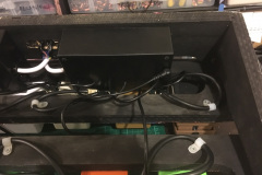
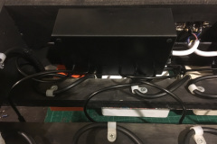
The last hurrah. I ordered some custom patch cables for this build and also ordered some custom, sealed power connectors because if you get the non sealed ones, the ends can touch the casing of MXR pedals and cause all sorts of issues. I housed the power supplies in some plain plastic boxes underneath the board and mounted the IEC plug directly into the wood. All in all I think it turned out extremely well, and it was finally done.
I won’t be doing a materials list this time as it was so long ago I build this the listings and links are all dead.

0 Comments